LinPro static analysis of plane frames
www.siljak.ba

new fresh place: www.siljak.ba
::: Example
::: Theory
::: eness@bosnia.ba
:::
Free download LinPro275_Setup.rar (1.5 MB)
 Example
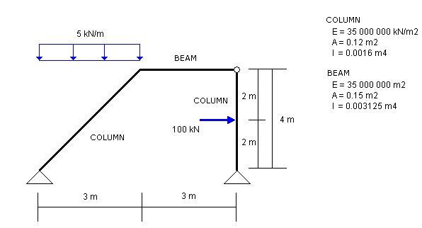
Draw the deflection line, axial force, shear force and bending moment diagram for the structure shown in figure:
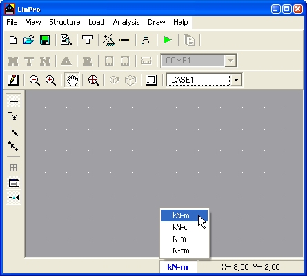
Main Window
On status bar select units that you are going to use. For this example select kN-m
Nodes and members you can define in main window using tools from toolbar Structure.
These tools you can find in pop-up menu with right click in working area of main window.
Defining Cross Sections
In menu Structure click on  Cross Section.
In the next window you can define cross section properties and material.
Cross Section.
In the next window you can define cross section properties and material.
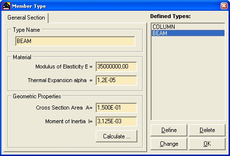
Input values and click on button Define and cross section name will be added to the list Defined Types
Defining Coordinates of joints/supports
From menu Structure select
 Coordinates of Joints/Supports and input coordinates of joints.
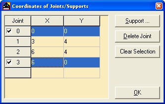
Here, you will define supports. In window Coordinates of Joints/Supports
click on joint number that should have support (in this example joints 3 i 0)
and button Support ...
will be enabled. Clicking on button Support ... you will open next window
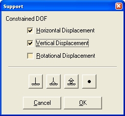
and here you will define proper supports. After defining support close window clicking on button OK.
Hide grid clicking on
 Show Grid
in menu Draw to stretch drawing on all working area.
Show Grid
in menu Draw to stretch drawing on all working area.
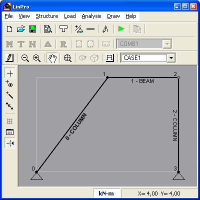
The main window should look like on the next picture:
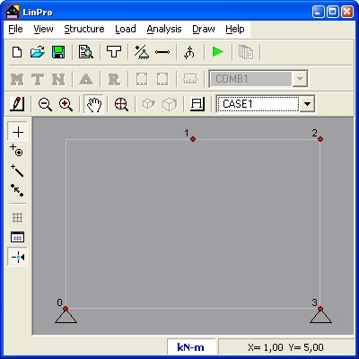
Some usual supports you can define from main window. Click with right mouse button on joint and you'll get pop-up menu. If you want to define support that does not exist in this pop up menu, for example horizontal reaction, then follow procedure described in previous section.
If you want to modify structure with pop-up menus structure have to be drawn. (menu : Draw -> Structure)
Position of members
In menu Structure
click on  Position of members. In the next window define members with end joints. In the same window assign cross section to member.
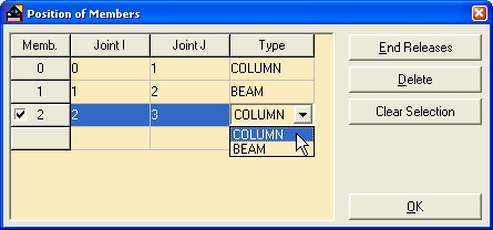
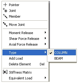
Member type can be assigned from main window. Click with right mouse button on member and you'll get pop up menu. Select Type and then select member type.
Defining hinge between members 1 and 2.
In window Position of members
click on member number (here member 1) and button End Releases will be enabled. Click on button End Releases and select Bending Moment at Joint 2.
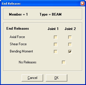
 You can define hinge between members 1 and 2 releasing moment at member 2 at joint 2, but not releasing moment at both members at the same joint i.e. in every joint at least one member have to be fixed.
On figure left is example with releasing axial and shear forces that will cause singularity of stiffness matrix.
You can define hinge between members 1 and 2 releasing moment at member 2 at joint 2, but not releasing moment at both members at the same joint i.e. in every joint at least one member have to be fixed.
On figure left is example with releasing axial and shear forces that will cause singularity of stiffness matrix.
If you release moment on every member, program will draw joint with red color emphasizing error, but if you release axial and shear forces (as on figure) error will be reported at running analysis.
End releases can be defined from main application window from pop-up menu (right click on member).
Close all windows clicking on OK.
Main application window should look like on the next picture.
Click on Write Member's Type Name in menu Draw if you want type names to be drawn.
Defining Load
In menu Load click on  Load on Joint/Member
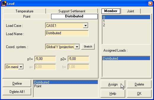
Defining uniform load on member 0
Chose Global Y (projection) Coord system;
Input -5 for p1 and p2;
Distaces of begining and ending of load form joint i can be defined as:
- absolute distaces
defined as a=0 b=3 and Absolute from list for distances,
- relative distaces
defined as a=0 b=1 and Relative from list for distances,
- on member
you only chose On member from list for distances
Since load acts on the whole member chose On member from list for distances.
If you want to define uniform load On member you can input value for p1 and then pres key Q on keyboard.
Now click on button Define and load will be defined and its name will be added to the list with defined loads.
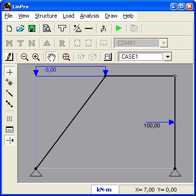
Defining point load on member 2
Chose Global coord. system;
Distance of point load from joint i can be defined as:
- absolute distance
defined as a=2 and Absolute form the list for distances
- relative distance
defined as a=0.5 i Relative from the list.
Input intensity:
X=100
Y=0
M=0
Click on button Define and point load will be defined and its name will be added to the list with defined loads.
Now you have to add loads to members.
Select distributed load in the list with defined loads, select member 0 in the member list and click on button Assign.
Load will be added to the list Assigned loads
Repeat the same procedure with point load and member 2
Close window Load.
Main window should look like on the next picture:
Analysis
After you have defined structure and load click on menu item  Run in menu Analysis
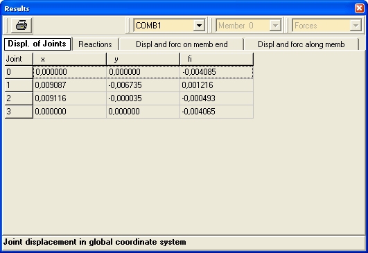
Results
Free body diagrams you can draw with commands in menu Draw or from toolbar  .
Results in table form you can get form menu Analysis ->
.
Results in table form you can get form menu Analysis ->  Tabulate Results
Theory
Stiffness matrix that is used by program is shown in the next figure:
Note that shear deformations are neglected.
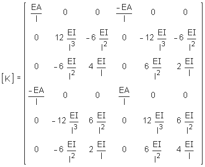
Cholesky-solver is used for solution of system of equations.
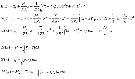
Calculation of deformations and forces along the member are based on the functions shown in the next figure.
That means that deformations and forces along member are accurate without dividing member into smaller pieces no matter what load is applied on member. (Accurate inside linear elastic theory without consideration of shear deformations).
::: Example
::: Theory
::: eness@bosnia.ba
:::
Free download LinPro275_Setup.rar (1.5 MB)